
Page 241 - Water Standards
P. 241
shall be no larger than 0 25mm and the total length shall
be no larger than 25% of the guide vane height.
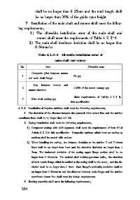
7 Installation of the main shaft and runner shall meet the follow⁃
ing requirements:
1) The allowable installation error of the main shaft and
runner shall meet the requirements of Table 4 2 5-4.
2) The main shaft levelness deviation shall be no larger than
0 04mm/ m
Table 4 2 5-4 Allowable installation error of
main shaft and runner
No Item Allowable error
Composite joint between runner
1 No gap
and main shaft flange
Gap between runner and
2 ±20% of the actual average gap
runner chamber
Meet requirements of Article 4 2 3 in
3 Main shaft sealing gap
this specification
4 2 6 Installation of impulse turbines shall meet the following requirements:
1 The deviation of the distance between the penstock inlet center line and the turbine
coordinate lines shall be no larger than ±0 2%
2 Casing installation shall meet the following requirements:
1) Compound casings with split segments shall meet the requirements of Item 10 of
Article 4 2 2 in this specification. Composite surfaces which have no sealing or
cushion shall be coated with sealant.
2) When installing the casing, the distance deviation to the turbine X and Y datum
lines shall be no larger than 1mm and the elevation deviation no larger than ±
2mm. The horizontal deviation of the casing upper flange surface shall be no
larger than 0 04mm/ m. For vertical shaft turbine⁃generator units, the elevation
of each nozzle flange which is welded to the casing shall be the same, and the de⁃
viation shall be no larger than 1 0mm. Each flange s verticality deviation shall be
no larger than 0 30mm/ m and the distance between each flange and the turbine
coordinate datum line shall meet the design requirements.
3 Bearing assembly shall meet the following requirements:
2 3 4