
Page 246 - Water Standards
P. 246
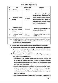
Table 4   2   7-3 (Continue)

             No        Item       Allowable error     Explanation
             2     Elevation        ±5   0mm             —

                                                 For  electro⁃hydraulic  type,
                                              measure the base of the electro⁃hy⁃
                   Mechanical cabinet         draulic conversion device; for me⁃
             3                     0   15mm/ m
                 levelness                    chanical hydraulic type, measure the
                                              bottom plate of the pendulum electric
                                              motor (the upper diaphragm)


                   Emergency distribu⁃
                                                Measure the foundation plate of the
             4   tion valve verticality  0   15mm/ m
                                              emergency distribution valve
                 or levelness
                    Electrical cabinet          Measure by lead weigh in the X
             5                     1   0mm/ m
                 verticality                  and Y directions
              Note: During the installation of combined speed controllers, the supports of the speed
                  controlling shaft  s transmission mechanism shall be taken as datum and the devia⁃
                  tion shall meet the design requirements

               8  Governors which need to be dismantled shall meet the following requirements:
                 1) For mechanical hydraulic parts which need to be dismantled in the electro⁃hydrau⁃
                   lic governor, component cleaning, assembly and adjustment shall meet the re⁃
                   quirements of the manufacturer drawings.
                 2) The cleaning, assembly and adjustment of the mechanical governor components
                   shall meet the following requirements:
                   —The connection of the pendulum electric motor and centrifugal pendulum shall
                    be concentric and be able to rotate freely. The radial and axial throw of the dia⁃
                    mond centrifugal pendulum spring seat relative to the steel belt upper support
                    shall be no larger than 0   04mm.
                   —When the buffer piston moves up and down and returns to the middle position,
                    the time spent in the last 1mm shall meet the design requirements. The differ⁃
                    ence between the upward and downward returning times shall be no larger than
                    10% of the setting time.
                   —If the permanent speed droop (residual degree of unbalance) is indicated to be
                                                                 2 3 9