
Page 243 - Water Standards
P. 243
radial deviation shall be no larger than ±2% d 1 (d 1 is the runner pitch diame⁃
ter). The axial deviation compared with the bucket water dividing edge shall be
no larger than ±0 5% W (W is the bucket maximum inner width).
—The deviation between the deflector center and nozzle center shall be no larger
than 4mm.
—The deviation between the buffer spring compression length and the design value
shall be no larger than ±1mm.
—The synchronous deviation of each jet nozzle through the stroke shall be no
larger than 2% of the design stroke.
—The axial and radial deviations of the reversed braking nozzle s center line shall
be no larger than ±5mm
6 Runner installation shall meet the following requirements:
1) The rotating surface of the runner bucket s water dividing edge shall pass through
the nozzle flange s center on the casing and the deviation shall be no larger than ±
0 5%W.
2) The amount of bouncing of the runner end face shall be no larger than 0 05mm/ m.
3) The gap between the runner and water flap shall meet the design requirements.
7 Main shaft sealing shall meet the requirements of Article 4 2 3 in this specification
8 Control mechanism installation and adjustment shall meet the following requirements:
1) The center deviation of each component of the control mechanism shall be no
larger than 2mm and the elevation deviation shall be no larger than ± 1 5mm.
Horizontal or vertical deviation shall be no larger than 0 10mm/ m. The mecha⁃
nism shall move freely after the installation.
2) The deflector opening shall be 3mm larger than the radius of the jet during this o⁃
pening stroke but shall be no larger than 6mm. Each deflector shall move synchro⁃
nously and the deviation shall be no larger than 2% of the design value
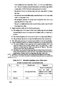
4 2 7 Installation of the speed governing system shall meet the following requirements:
1 The allowable error of the oil pressure device installation shall meet the requirements
of Table 4 2 7-1
Table 4 2 7-1 Allowable installation error of the return
oil tank (governor tank) and pressure tank
No Item Allowable error Explanation
Measure the distance be⁃
tween the marks on
1 Center No larger than 5 0mm equipment and the turbine⁃
generator X and Y datum
lines
2 Elevation ±5mm —
2 3 6