
Page 238 - Water Standards
P. 238
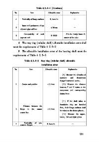
Table 4   2   5-1 (Continue)

             No          Item          Allowable error   Explanation

             4     Verticality of flange surfaces  0   4mm/ m  —

                   Inner wall perimeters of two
             5                           ≤10mm              —
                 adjacent pipe orifices
                    Concentricity  of  each           D is the design inner di⁃
             6                           0   002D
                 segment unit                       ameter of the pipe
               4  The stay ring (tubular shell) allowable installation error shall
           meet the requirements of Table 4   2   5-2
                5  The allowable installation error of the bearing shall meet the
           requirements of Table 4   2   5-3
                     Table 4   2   5-2  Stay ring (tubular shell) allowable
                                  installation error

             No         Item         Allowable error   Explanation
                                                  (1) Measure the elevation of
                                                 upstream  and  downstream
                                                 flanges   horizontal marks;
             1     Center and position  ±2   0mm  ( 2 ) Measure the distance
                                                 between X and Y marks on the
                                                 component and  corresponding
                                                 datum lines


                                                  ( 1 ) If the draft tubes or
                                                 foundation ring are installed
                    Distance between the
                                                 first, their flange surfaces shall
             2   flange  to  the  runner  ±2   0mm
                                                 be taken as the datum planes;
                 center line
                                                  ( 2 ) Measure the upper,
                                                 lower, left and right points
                    Verticality  of  pre⁃
             3                        0   8mm/ m          —
                 centrum flanges

                                                                 2 3 1