
Page 237 - Water Standards
P. 237
sealing surfaces shall be no larger than 0 08mm.
5) The end clearance between the guide vane seals and front and back cover plates
shall be no larger than 0 25mm.
3 The checking and scraping of the bearing liner shall meet the requirements of Article
4 2 9 in this specification
4 The fitting between the bearing liner and the bearing shell shall meet the
requirements of Article 4 2 9 in this specification
5 The bearing liner gap shall meet design requirements and shall be closely sealed up.
The oil shall be able to recycle smoothly.
4 2 5 Installation of shaft⁃extension tubular turbines shall meet the following requirements:
1 For parts which need to be preassembled on site, when being hoisted up and turned
over by 90°, measures shall be taken to prevent deformation and overturning. The embedded
parts shall be reinforced after the installation and adjustment. The concrete shall be poured
layer by layer and the rising speed shall be controlled to prevent the deformation of the parts
2 Fitted components shall be preassembled and the fit size shall be checked before be
hoisted. Any deviation which exceeds the allowable error shall be corrected before installa⁃
tion
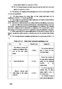
3 The draft tube allowable installation error shall meet the requirements of Table 4 2 5
-1
Table 4 2 5-1 Draft tube s allowable installation error
No Item Allowable error Explanation
The difference between the
For structures with base
maximum and minimum diam⁃
1 3 0mm ring, it means the base
eters of the pipe orifice
ring upper flange
flanges
Measure the elevation of
the pipe orifice s horizontal
2 Center and elevation ±1 5mm marks and the horizontal
deviation of the
vertical marks
(1) If the stay ring is
installed first, its flange
Distance between pipe
surface shall be taken as
3 orifice flange to the runner ±2 0mm
the datum plane;
center line
(2) Measure the upper,
lower, left and right points
2 3 0