
Page 232 - Water Standards
P. 232
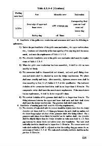
Table 4   2   3-4 (Continue)

             Working
                            Part           Allowable error  Explanation
            water head
                                                        Corresponding fixed
                      Outer edge of upper and             parts are head
                                          ±5% of design gap
             ≥200m        lower crown                       cover and
                                                           bottom ring
                          Sealing ring      ±0   10mm         —
               3  Installation of the guide vane mechanism and servomotor shall meet the following re⁃
           quirements:
                 1) Before the pre⁃installation of the guide vane mechanism, the upper surface eleva⁃
                   tion, levelness and circularity of the bore opening of the stay ring shall be remea⁃
                   sured, and meet the requirements of Table 4   2   3-2.
                 2) The allowable installation error of the guide vane mechanism shall meet the require⁃
                   ments of Table 4   2   3-5.
                 3) When the guide vane mechanism has been assembled, it shall be able to move
                   steadily and freely.
                 4) The servomotor shall be disassembled and cleaned, and each part  s fitting clear⁃
                   ance and stroke shall be checked to meet the design requirements. The piston
                   shall move steadily and freely. After assembly, tightness pressure tests shall be
                   done according to Item 14 of Article 4   2   2 of this specification. The horizontal
                   deviation of the servomotor installation shall be no larger than 0   10mm/ m. The
                   compression stroke shall meet the manufacturer requirements. If the manufacturer
                   has no requirements, it shall be in the range of 3-6mm.
                 5) The vertical deviation of the governor shaft shall be no larger than 1mm/ m. The
                   fitting clearance between the upper and lower shaft neck and their shaft sleeve
                   shall meet the design requirements. The governor shaft shall rotate freely
               4  Installation of rotating parts shall meet the following requirements:
                 1) The elevation of main shaft with the runner should be slightly lower than the design
                   elevation and there shall be a 2-6mm gap between the main shaft top surface and
                   the lower flange spigot sub⁃face of the generator shaft after being hoisted. For a
                   generator unit whose thrust block is installed on the turbine shaft, the elevation
                   shall be slightly higher than the design elevation to make sure there is a 2-5mm
                   gap between the thrust block and mirror plate after installation. The main shaft
                   verticality deviation should not be larger than 0   05mm/ m. The runner center and
                   main shaft verticality shall be adjusted so that the sealing ring gap meets the re⁃
                   quirements of Table 4   2   3-6. The main shaft verticality deviation shall be no lar⁃
                   ger than 0   02mm/ m.
                                                                 2 2 5