
Page 231 - Water Standards
P. 231
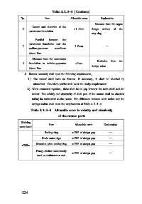
Table 4   2   3-3 (Continue)

             No           Item          Allowable error  Explanation
                                                      Measure from the upper
                   Center and elevation of the
             6                            ±1   0mm  flange  surface  of  the
                 servomotor foundation
                                                    stay ring
                     Parallel  between  the
                 servomotor foundation and the
             7                            1   0mm           —
                 turbine⁃generator  coordinate
                 datum line
                   Distance from the servomotor
                                                       Deviation  from  the
             8   foundation to turbine⁃generator  ±3mm
                                                    design value
                 datum line
               2  Runner assembly shall meet the following requirements:
                 1 ) The runner shall have no fissures. If necessary, it shall be checked by
                   ultrasound. The blade profile shall meet the design requirements.
                 2) When connected together, there shall be no gap between the main shaft and the
                   runner. The axiality and circularity of each part of the runner shall be checked
                   taking the main shaft as the center. The difference between each radius and the
                   average radius shall meet the requirements of Table 4   2   3-4
                  Table 4   2   3-4  Allowable error in axiality and circularity
                                 of the runner parts
             Working
                            Part           Allowable error  Explanation
            water head
                          Sealing ring   ±10% of design gap   —
                        Blade outer edge  ±10% of design gap  —
                     Diversion plate sealing ring  ±15% of design gap  —
             <200m
                     Flange shelter concurrently
                                         ±15% of design gap   —
                      used as maintenance seal


             2 2 4