Page 230 - Water Standards
P. 230

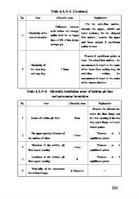
Table 4   2   3-2 (Continue)

             No      Item        Allowable error       Explanation
                                                  For the axial⁃flow turbine,
                                 Difference  between
                                               measure the upper, middle and
                              each radius and average
                 Circularity of the            lower sections; for the diagonal
             4                radius shall be no larger
                  runner chamber               flow turbine, measure the upper
                              than ±10% of the design
                                               and lower spigots 8 equidistant
                              average gap
                                               points at least
                                                 Measure 8 equidistant points at
                                               least. For mixed⁃flow turbine, the
                  Circularity of               measurement is based on the center
             5    the base ring    1   0mm     of the lower fixed sealing ring; for
                  and stay ring                axial⁃flow  turbine,  the
                                               measurement is based on the center
                                               of the runner chamber
                Table 4   2   3-3  Allowable installation error of turbine pit liner
                              and servomotor foundation

             No           Item          Allowable error  Explanation
                                                      Measure the distance be⁃
                                                    tween the liner flange and
             1     Center of turbine pit liner  5mm  the bore opening of the stay
                                                    ring upper flange at 8 equi⁃
                                                    distant points
                   The upper opening diameter of        Measure  at  8
             2                             ±5mm
                 the turbine pit liner              equidistant points
                   Elevation of the turbine pit         Measure  at  8
             3                             ±3mm
                 liner upper opening                equidistant points
                   Levelness of the turbine pit         Measure  at  8
             4                              6
                 liner upper opening                equidistant points
                    Verticality of the servomotor
             5                           0   30mm/ m        —
                 foundation flanges


                                                                 2 2 3
   225   226   227   228   229   230   231   232   233   234   235