
Page 199 - Water Standards
P. 199
shall meet the requirements of Table 4 1 2-2.
8) For tainter gates which run under high water
head with sudden expansion gate slots, the
maximum deviation of the distance between the
side track s water stop seat base surface center
line and the sluice hole center line is ±2 0
mm; the maximum deviation of the side track s
water stop seat base surface curvature radius is
±3 0mm, and the deviation direction shall be
in accordance with the deviation direction of the
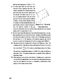
Figure 4 1 2 Tilt of the
gate leaf outer cambered surface s curvature ra⁃
hinge steel beam
dius; the maximum deviation of the gap
between the side track s water stop seat base surface and gate leaf outer cambered
surface shall be no larger than ±1 5mm.
9) When the steel beam of the tainter gate hinge is installed independently, the max⁃
imum deviation of the steel beam center s travel, elevation and the distance to the
center line of the sluice hole shall be ±1 5mm. The tilt of the hinge steel beam is
shown in Figure 4 1 2. The deviation of the horizontal projection size shall be
controlled to ensure that the deviation of L shall be no larger than1/ 1000 of L.
10) The maximum elevation deviation of the horizontal steel lining is ±1 5mm. The
maximum deviation of the distance between the lateral steel lining and the sluice
+6 0
hole center line is mm. The maximum surface flatness tolerance is 4 0mm.
-2 0
The maximum perpendicularity tolerance is 1/ 1000 of the height and shall be no
larger than 4 0mm. The staggered displacement of composite surfaces shall be no
larger than 2 0mm.
11) When embedded parts have been well adjusted, adjusting screws, anchor slabs
and bolts shall be welded firmly as per the requirements of the design drawings to
make sure that embedded parts have no deformation or displacement in the
process of second⁃stage concrete casting.
1 9 2