
Page 198 - Water Standards
P. 198
the second⁃stage concrete, the section size and the
position of embedded anchor slabs, bolts and bars shall
meet the design drawing requirements.
3) When the embedded parts of plane gates are installed, the
allowable error shall meet the requirements in DL/ T 5018.
4) The installation of embedded parts for plane sprocket gates
shall meet the requirements in DL/ T 5018 and the
staggered displacement at the joints of the main track bear⁃
ing face shall be no less than 0 2mm. The joints shall be
processed to be gentle slopes. The main track bearing
faces on both sides of the sluice hole shall be on the same
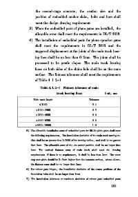
surface. The flatness tolerance shall meet the requirements
of Table 4 1 2-1
Table 4 1 2-1 Flatness tolerance of main
track bearing faces Unit: mm
Main track length Tolerance
≤1000 0 4
>1000-2500 0 5
>2500-4000 0 6
>4000-6300 0 8
>6300-10000 1 0
5) The allowable installation error of embedded parts for lift⁃lie plain gates shall meet
the following requirements: The installation deviation of the main track turning ra⁃
dius shall be no greater than 1/ 1000 of the turning radius, and shall be no greater
than 2mm. The allowable error of the arc center position shall be no larger than
2mm. The vertical flatness error of main track shall meet the drawing
requirements. If there is no requirement, it shall be less than 2mm. The water
stop seat plate should be 3-5mm higher than the concrete surface, whose allowa⁃
ble flatness error shall be no larger than 2mm.
6) For tainter gate hinges, the installation deviation of the center positions of the
foundation bolts shall be no larger than 1mm.
7) The installation tolerance or maximum deviation of tainter gate embedded parts
1 9 1