
Page 265 - Water Standards
P. 265
space for component assembly and welding.
2) When the butterfly valve has been installed, the center
line in the flow direction shall be determined according to
the actual centers of the spiral case and penstock. The de⁃
viation between the actual and design positions should not
be larger than 3mm. The position deviation ( be perpen⁃
dicular to the flow direction) should not be larger than
10mm. The butterfly valve s horizontal and vertical devia⁃
tions shall be no larger than 1mm/ m measured after flange
welding. In case of butterfly valves of diameter larger than
4 0m, the deviation shall be no larger than 0 5mm/ m.
3) For convenience of moving the butterfly valve towards the
expansion joint when overhauling, enough distance shall
be left between the base bolts and bolt holes. The distance
shall be no less than the diameter of the rubber packing
between flanges.
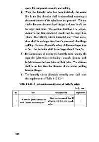
4) The butterfly valve s allowable assembly error shall meet
the requirements of Table 4 2 12-1
Table 4 2 12-1 Allowable assembly error of butterfly valves
Unit: mm
No Item Allowable error Explanation
Meet requirements of Item 10
Composite joints between the
1 of Article 4 2 2 in this specifi⁃ —
valve seat and foundation plate
cation
2 5 8