
Page 259 - Water Standards
P. 259
ble 4 2 9-1
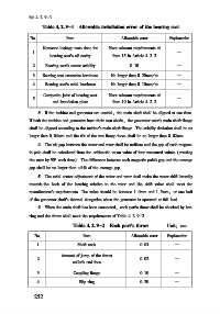
Table 4 2 9-1 Allowable installation error of the bearing seat
No Item Allowable error Explanation
Kerosene leakage tests done for Meet relevant requirements of
1 —
bearing seat s oil cavity Item 15 in Article 4 2 2
2 Bearing seat s center axiality 0 10 —
3 Bearing seat crosswise levelness No larger than 0 20mm/ m —
4 Bearing seat s axial levelness No larger than 0 10mm/ m —
Composite joint of bearing seat Meet relevant requirements of
5 —
and foundation plate Item 10 in Article 4 2 2
3 If the turbine and generator are coaxial, the main shaft shall be aligned at one time.
If both the turbine and generator have their own shafts, the generator rotor s main shaft flange
shall be aligned according to the turbine s main shaft flange. The axiality deviation shall be no
larger than 0 04mm and the tilt of the two flange faces shall be no larger than 0 02mm
4 The air gap between the stator and rotor shall be uniform and the gap of each magnet⁃
ic pole shall be calculated from the arithmetic mean value of four measured values (rotating
the rotor by 90° each time). The difference between each magnetic pole s gap and the average
gap shall be no larger than ±8% of the average gap
5 The axial center adjustment of the stator and rotor shall make the stator shift laterally
towards the back of the bearing relative to the rotor and the shift value shall meet the
manufacturer s requirements. The value should be between 1 0mm and 1 5mm, or one half
of the generator shaft s thermal elongation when the generator is operated at full load
6 When the main shaft has been connected, each part s throw shall be checked by bar⁃
ring and the throw shall meet the requirements of Table 4 2 9-2
Table 4 2 9-2 Each part s throw Unit: mm
No Item Allowable error Explanation
1 Shaft neck 0 03 —
Amount of jump of the thrust
2 0 02 —
collar s end face
3 Coupling flange 0 10 —
4 Slip ring 0 20 —
2 5 2